i1=EmSinωt/(Rf+RL) = ImSinωt ( when 0≤ωt≤π)
= o ( when π ≤ωt≤2π)
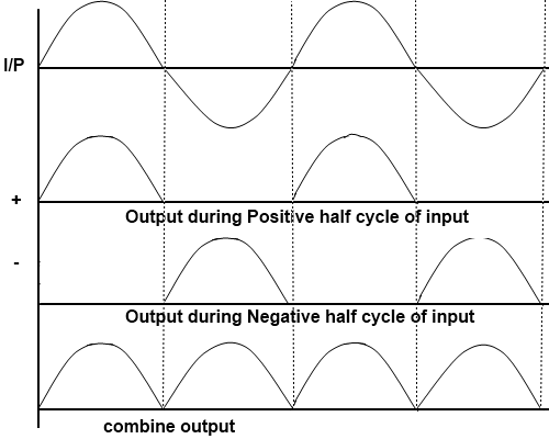
During the second half of each power cycle,e2N is positive and e1N is negative. Therefore diode D2 conducts and current i2 flows through RL .This current is obtained as
i2=EmSinωt/(Rf+RL) = ImSinωt ( when π≤ωt≤2π)
= o ( when 0≤ωt≤π)
The current through the load is the sum of i1 and i2 and unidirectional in the whole cycle. The below figure shows the profile of currents i1 and i2 and i. The DC current is
idc =1/2π [∫ ImSinωtd(ωt) + ∫ ImSinωtd(ωt) ] (first integral is integrated over o to π and second integral is integrated over π to 2π)
idc = 2Im/π
The rms current is given by
I = [1/2π∫i²d(ωt)]0.5 (limit of the integration is from o to 2π)
= [1/2π∫I²mSin²ωtd(ωt)]0.5
= Im/√2
It is seen that both Idc and I in this circuit are twice of those in the half wave circuit.
The voltage across the load is (iRL).
Vm = EmRL/(Rf+RL)
Vdc = EmRL/π(Rf+RL)
V = EmRL/√2(Rf+RL)
The dc power delivered to the load is obtained as
Pdc = I² dc*RL = 4E²m*RL/π²(Rf+RL)²
The efficiency of Full Wave circuit is obtained as
Pin = I²(Rf+RL) = E²m/2(Rf+RL)
The efficiency of the Full Wave rectifier , is obtained as
η = Pdc/ Pin = 0.812/(1+ Rf+RL)


No comments:
Post a Comment