Ripple Factor and some key points of Half Wave Rectifier

 The value of ripple factor of single phase half wave rectifier is equal to 1.21. Since, ripple factor is the ratio of RMS value of fluctuating ac component to the average value or dc value. Its value of 1.21 means that, the ac fluctuating component in the rectified output of half wave rectifier is 121% of the expected DC output or average vale. This simply means, the rectification is poor as the ripple content is even higher than the DC output. Let us now see the calculation of this ripple factor.

Calculation of Ripple Factor of Half Wave Rectifier:

The circuit diagram of single phase half wave rectifier is shown below.

Half Wave Rectifier Circuit Diagram

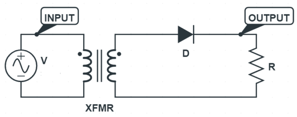
The diode will be forward biased for the positive half cycle of the supply whereas it will be reverse biased for the negative half cycle. Thus the diode will conduct only for the positive half cycle and will not conduct for the negative half cycle. Therefore, current output will only be conducting and allowing the current to flow just for the positive half cycle of the supply. This is the reason; it is called single phase half wave rectifier.

The output waveform of half wave rectifier ignoring cut-in voltage is shown in figure below. Blue color depicts the supply voltage whereas red color denotes the rectifier output current.

This output current can be defined as

Half Wave Rectifier output current

i = Imsinωt for 0≤ωt≤π

  = 0 for π≤ωt≤2π

Let us now find the RMS value and average value of this current to find the ripple factor of half wave rectifier.

derivation of rms value of half wave rectifier

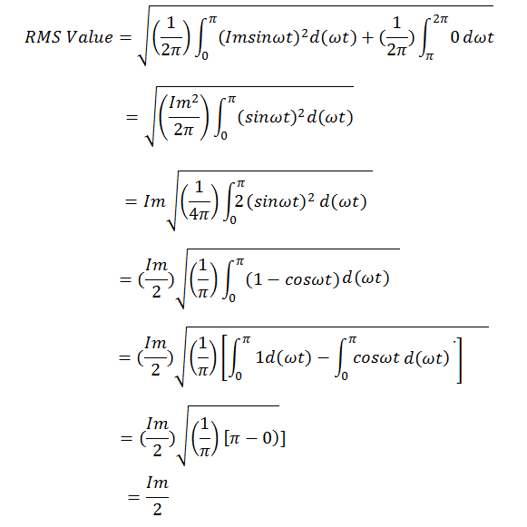
Thus, the RMS value of current output of half wave rectifier is 0.5 times of the peak current i.e. 0.5Im.

The average value of single phase half wave rectifier is equal to 0.318 times of peak current i.e. 0.318Im

Now, the ripple factor of half wave rectifier can easily be calculated from the formula.

ripple factor formula

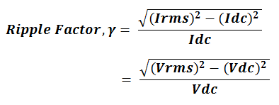
Putting the value of RMS current and average current, the value of ripple factor can easily be calculated from the above formula.

Value of ripple factor of half wave rectifier

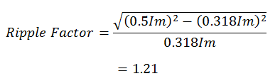
Thus, the value of ripple factor of half wave rectifier is 1.21.


Advantages and Disadvantages of Half wave rectifier:

Advantages

The advantage of a half wave rectifier is only that its cheap, simple and easy to construct. It is cheap because of the low number of components involved. Simple because of the straight forwardness in circuit design. Apart from this, a half wave rectifier has more number of disadvantages than advantages.

Disadvantages

A half wave rectifier is rarely used in practice. It is never preferred as the power supply of an audio circuit because of the very high ripple factor. High ripple factor will result in noises in the input audio signal, which in turn will affect audio quality.

1. The output current in the load contains, in addition to dc component, ac components of basic frequency equal to that of the input voltage frequency. Ripple factor is high and an elaborate filtering is, therefore, required to give steady dc output.

2. The power output and, therefore, rectification efficiency is quite low. This is due to the fact that power is delivered only during one-half cycle of the input alternating voltage.

3. Transformer utilization factor is low.

4. DC saturation of the transformer core resulting in magnetizing current and hysteresis losses and generation of harmonics.

The  DC output available from a half-wave rectifier is not satisfactory to make a  general power supply. However, it can be used for some applications like battery charging. 


Mathematical Analysis of a Full Wave Rectifier

During the first half of each power cycle,e2N is negative and e1N is positive. Therefore diode D1 conducts and current i1 flows through RL .This current is obtained as


i1=EmSinωt/(Rf+RL) = ImSinωt ( when 0≤ωt≤π)

                                 = o   ( when π ≤ωt≤2π)

During the second half of each power cycle,e2N is positive and e1N is negative. Therefore diode D2 conducts and current i2 flows through RL .This current is obtained as 

 i2=EmSinωt/(Rf+RL) = ImSinωt ( when  π≤ωt≤2π)

                                 = o   ( when 0≤ωt≤π)

The current through the load is the sum of i1 and i2 and unidirectional in the whole cycle. The below figure shows the profile of currents  iand i2 and i. The  DC current is  

                  idc =1/2π [∫ ImSinωtd(ωt) + ∫ ImSinωtd(ωt) ] (first integral is integrated over o to π and second integral is integrated over π to 2π)

                           idc =  2Im/π

The rms current is given by

                             I =  [1/2π∫i²d(ωt)]0.5 (limit of the integration is from o to 2π)

                               =   [1/2π∫I²mSin²ωtd(ωt)]0.5

                                =  Im/√2

It is seen that both Idc and  in this circuit are twice of those in the half wave circuit.

The voltage across the load is (iRL).


Also

Vm  = EmRL/(Rf+RL

Vdc = EmRL/π(Rf+RL)

V    = EmRL/√2(Rf+RL) 

The dc power delivered to the load is obtained as

                               Pdc = I² dc*RL = 4E²m*RL/π²(Rf+RL)²

The efficiency of Full Wave circuit is obtained as 

                              Pin = I²(Rf+RL) = E²m/2(Rf+RL)

The efficiency of the Full Wave rectifier , is obtained as 

                                        η = Pdc/ Pin  = 0.812/(1+ Rf+RL)


Full Wave Rectifier and it's comparison with Half Wave Rectifier

Full Wave Rectifier and it's benefit over Half Wave Rectifier:

 Although the half wave rectifier is used in some low power applications such as signal and peak detector, it is seldom used in power rectification. The most used rectifier in the power rectification field is the full wave rectifier.

The full wave rectifier is more complex than the half wave rectifier, but it offers some significant benefits. It uses both half cycles of the sine wave resulting in a DC output voltage that is higher than that of the half wave rectifier. Another advantage is that the output has much less ripples, which makes it easier to produce a smooth output waveform.

Circuit Diagram & operation of a Full Wave Rectifier:

To rectify both half cycles of a sine wave, the full-wave rectifier uses two diodes, one for each half of the cycle. It also uses a transformer with a center-tapped secondary winding.

The full-wave rectifier is like two back-to-back half-wave rectifiers. Following image shows a Full-wave rectifier circuit.

fullwave rectifier

Consider the first half-cycle, when point A is positive with respect to C. At this time, D1 is forward biased and D2 is reverse biased. Therefore, only the top half of the transformer’s secondary winding carries current during this half-cycle. This produces a positive load voltage across the load resistor.

fullwave rectifier during positive half cycle

During the next half-cycle, the source voltage polarity reverses. Now, point B is positive with respect to C. This time, D2 is forward biased and D1 is reverse biased. As you can see, only the other half of the transformer’s secondary winding carry current. This also produces a positive load voltage across the load resistor as before.

fullwave rectifier during negative half cycle

As a result, the rectified load current flows during both half-cycles due to which we get Full-wave signal across the load.

fullwave signal

What is Half wave rectifier and how does diode act as a half wave rectifier?

What is a Half Wave Rectifier?

 half wave rectifier is defined as a type of rectifier that only allows one half-cycle of an AC voltage waveform to pass, blocking the other half-cycle. Half-wave rectifiers are used to convert AC voltage to DC voltage, and only require a single diode to construct.

Circuit Diagram of a Half Wave Rectifier :

A half wave rectifier circuit diagram looks like this:


The above figure shows a half wave rectifier circuit in series with a resistance RL . If the applied voltage,  e = VmSinθt  then

i=Vmsinθt/(RRL) = ImSinθt (for 0≤θt≤π)

                                  =0 ( for π≤ θt≤2π)

Where Rf = resistance of diode in forward direction

Also Im=Em/(Rf+RL)


                              (Current waveform in Half wave rectifier circuit)

Let Rf and RL be the forward resistance & load resistance of the diode. v = Vm sin θ be the voltage appearing across the secondary of the power transformer. During the positive half cycle, the diode is forward biased making the current flow through the load resistor. While during the Negative half cycle the diode is reverse biased so it stops the current flow through the load resistor. The waveform diagram shows only a positive waveform at the output and a suppressed negative waveform. During the conduction period its instantaneous value is given by the equation: 

i = v / (Rf+RL )                                                                                                                      v = i(Rf+RL ) As we know, v = Vm sin θ Therefore, i = Vm sin θ /(Rf+RL ) When sin θ = 1, current = maximum. Therefore, Im = Vm /(Rf+RL )

Where, i = Im sinθ                                                                                                          As the output is obtained across RL, therefore 
                                              D.C power output = I²dcRL
                                                                           = *Iav2 RL 
 Where, Iav = ʃ (i dθ) / 2π   ….. (i) 
 Integrate equation (i) from 0 to π, 
                                                     Iav = (1 / 2π) * ʃ Im sin θ dθ 
                                                           = (Im / 2π) * ʃ sin θ dθ 
                                                           = (Im / 2π) [ – cos θ ]
                                                           = (Im / 2π) [ -(-1-1)]
                                                           = 2 (Im / 2π) 
                                                           = (Im / π)
 
Therefore, DC power output is given as, 
                                                            Pdc = I²dcRL  
                                                                  (Im / π)2RL

 AC power input is given as,
                                                         Pac =I2rms(Rf+ RL
Where,  Irms = ʃ (i2dθ) / 2π ….. (ii) 

Integrate equation (ii) from 0 to π,
                                                            = √ (1 / 2π) * ʃ I2msin2 θ dθ 
                                                            = √ (Im2 / 2π) * ʃ ( 1- cos 2θ)/ 2  dθ 
                                                            = √ (Im2 / 4π) * [ ʃ dθ – ʃ cos 2θ dθ ] 
                                                            = √ (Im2 / 4π) * [[θ] – [sin 2θ / 2]]
                                                            = √ (Im2 / 4π) * [π – 0]
                                                            = Im / 2 
Therefore, AC power input is given as, 
                                                               Pac =I2rms(Rf+ RL)
                                                                     = ( Im / 2)(Rf+ RL)

Rectifier Efficiency (η) = Pdc / Pac 
                                 η =[ (Im / π)2 * RL ] /( Im / 2)* (Rf+ RL
                                    = 0.406 RL / (Rf+ RL
                                    = 0.406 / [1+(Rf /RL )] 
If Rf is neglected as compare to RL then the efficiency of the rectifier is maximum. Therefore   ηmax =0.406 = 40.6%

This indicates that the half wave rectifier can convert maximum 40.6% of AC power into DC power, and the remaining power of 59.4% is lost in the rectifier circuit. Hence the half wave rectifier efficiency is 40.6% In fact, 50% power in the negative half cycle is not converted and the remaining 9.4% is lost in the circuit.